
M.H Ramezannia
CV site
Traffic light design using FPGA
Before starting the description of this project, it is better to get to know the FPGA board used in this project and its features from this link.
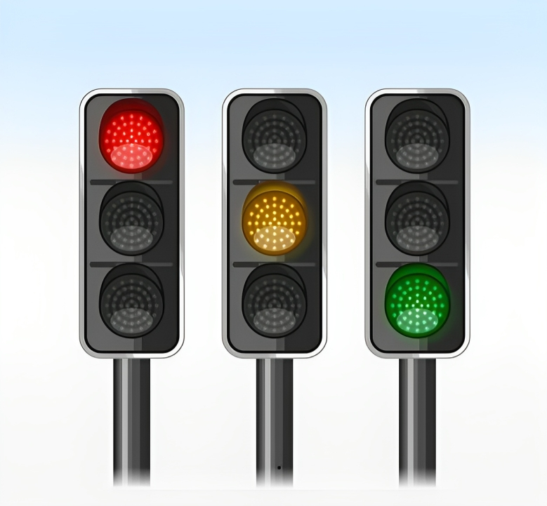
In this project, we are going to simulate a traffic light for a crossroads using FPGA. A traffic light for an intersection follows four consecutive steps as shown below.
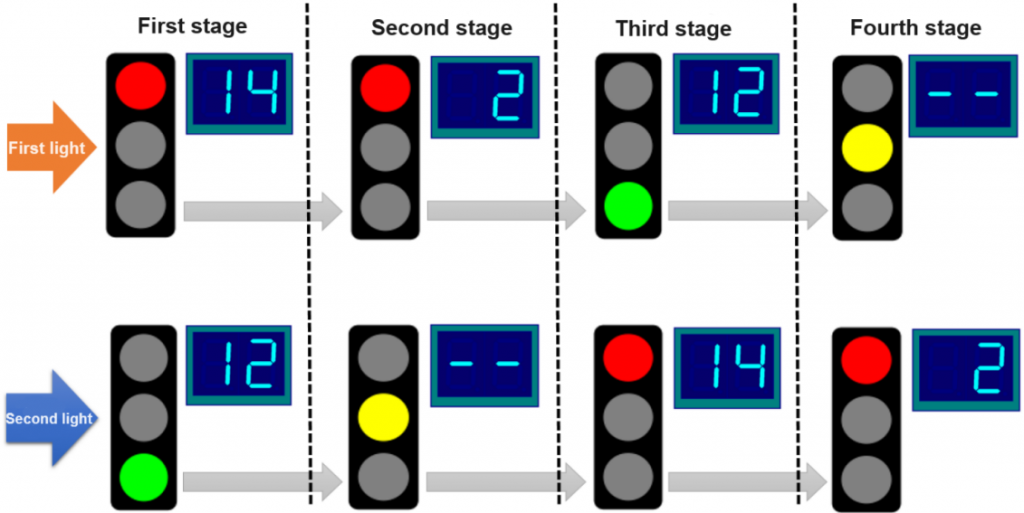
As is clear, the last two stages of the traffic light are the opposite of the first two stages. So, in order to code more effectively, we can write the code for the first two steps and then use the reverse of the first pattern for the lights for the next two steps.
The code we have written is supposed to do this: first, two numbers between 0 and 100 are entered through a dip switch, which is done with the rising edge of the “Apply” signal. Then this program compares two numbers and assigns the larger number to the duration of the red light, and the smaller number to the duration of the green light. Also, if the entered numbers are not valid (that is, the entered numbers are out of the specified range or the two numbers are equal), there will be no change in the previously registered numbers for the duration of the lights. Also, the difference between the duration of green and red lights is stored as the duration of yellow lights.
We also have another signal called “Blink”, which is applied through a dip switch, which makes it possible to set the system to traffic light or flashing light mode.
In this project, we used a 4 Digit 7 Segment Displays to show numbers, two of which are for one traffic light and the other two for another traffic light.

So, finally, we apply the numbers by dip switches and push buttons and also specify the working mode by using a Blink signal. Also, the FPGA output is connected to seven segments to display numbers and 6 LEDs to indicate two traffic lights.
The schematic of how it works is as follows:
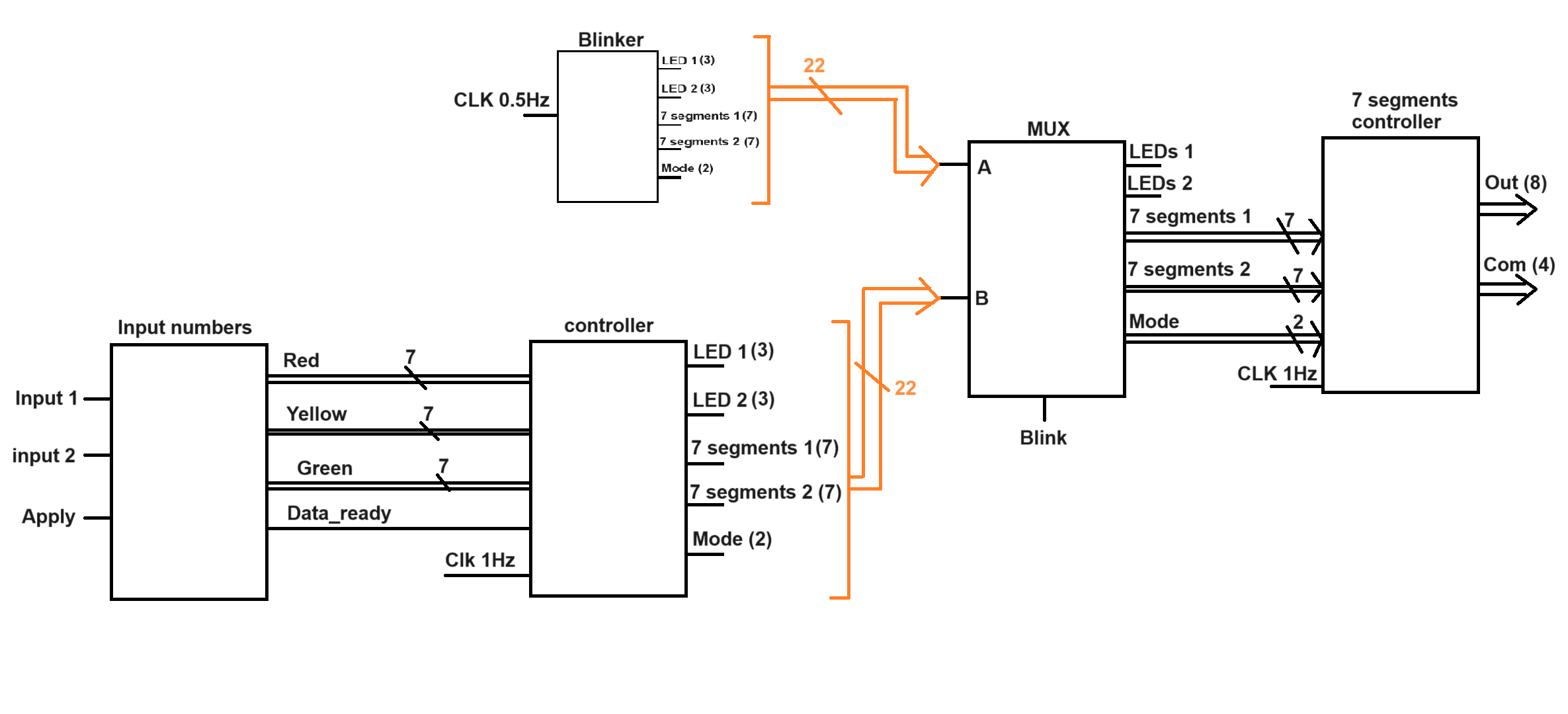
This design is done in a modular way and at the end the written modules are connected together.
The written codes of each part along with their connecting code are available in this link. Unfortunately, the modified codes after testing on the lab board are not available to me, and these existing codes also worked very well in the simulation, but on the day of the test, there were some small bugs that were fixed.
Description
University
May 6, 2023
In this project, with the help of FPGA, we were able to build a traffic light for a crossroads.