
M.H Ramezannia
CV site
Sine waveform generation by DAC with FPGA
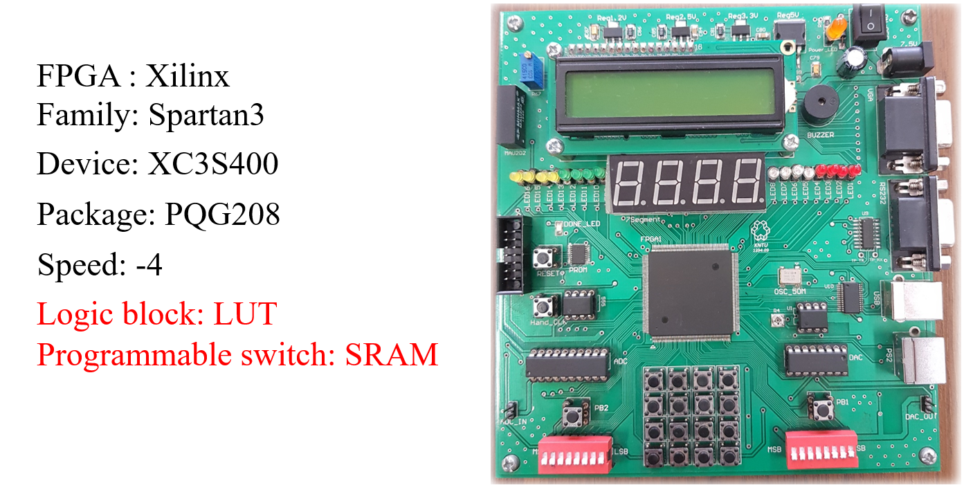
In this project, which is implemented with FPGA, we are going to make a sine wave with different amplitudes and frequencies using the DAC part of this chip. Below is a picture of the FPGA in the lab and its specifications.
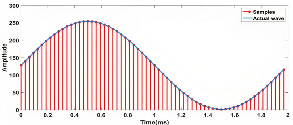
The module built in this project has a one-bit clock input, a two-bit input connected to the dip switch to enter the working mode, and an 8-bit output to connect and value to the DAC. First, to make a sine wave, it is necessary to generate a sine wave with a frequency of 500 Hz in MATLAB, and then we take 64 samples from it, and after converting the samples into 8-bit numbers, we store them in a 64-bit memory inside the FPGA.
Now, since 64 samples are taken from a 500 Hz sine wave, then the interval between both samples is equal to 31.25 microseconds. Therefore, the sampling frequency is equal to 32 kHz. Since the frequency of our FPGA board is 50 MHz, there must be a gap of about 1563 clocks between the two outputs of our sample connected to the DAC to generate a 500 Hz sine wave. And to generate 1/2 frequency, it is enough to double the time interval between two samples.
Now our project should work in four working modes. The first mode should produce a sine wave with a frequency of 500 Hz. In the second case, it should produce a sine wave with a frequency of 250 Hz. In the third case, it should produce a sine wave with a frequency of 125 Hz. And in the fourth mode, it should work with a frequency of 125 Hz, but with a half of the range of the previous modes.
First, we add the libraries:
library IEEE ;
use IEEE.STD_LOGIC_1164.ALL;
use IEEE.STD_LOGIC_arith.ALL ;
use IEEE.STD_LOGIC_unsigned.ALL;
Our device has a clock input, a two-bit input for four arbitrary states, and an 8-bit output connected to the DAC input.
entity sin_fer is
 port(clk : in std_logic;
   mode : in std_logic_vector(1 downto 0);
   out_dac : out std_logic_vector(7 downto 0);)
end sin_fer;
architecture Behavioral of sin_fer is
In this part, we first create a memory so that we can put the sampled values in it. The value given to us was a decimal number and we had to convert it to a binary number, so I wrote a program in C language and with the help of it, I converted the given numbers to a binary number and stored it in the memory of the program.
type memory is array(0 to 63) of std_logic_vector(7 downto 0);
signal hafeze :memory
:=("10000000","10001100","10011000","10100100","10110000","10111011","11000110","11010000","11011001","11100010","11101001","11110000","11110101","11111001","11111100","11111110","11111111","11111110","11111100","11111001","11110101","11110000","11101001","11100010","11011001","11010000","11000110","10111011","10110000","10100100","10011000","10001100","10000000","01110100","01101000","01011100","01010000","01000101","00111010","00110000","00100111","00011110","00010111","00010000","00001011","00000111","00000100","00000010","00000001","00000010","00000100","00000111","00001011","00010000","00010111","00011110","00100111","00110000","00111010","01000101","01010000","01011100","01101000","01110100");
We create a signal for the frequency counter (for frequency division) and a counter signal for browsing the stored memory. (The frequency of our chip is 50 MHz, and to reach 500 Hz, it must count 1563 times, and to reach 250 Hz, it must count 3126 times, and for 125 Hz, it must count 6225 times):
signal count_fer : std_logic_vector(12 downto 0):="0000000000000"; -- az 0 ta 6225
signal count_haf : integer range 0 to 63:=0;-- az 0 ta 63
begin
Clock-sensitive process and condition sensitive to the rising edge of the clock:
process(clk)
begin
if rising_edge(clk) then
Each time we have a rising edge, the frequency counter is incremented by one
count_fer <= count_fer+"000000000001";
For the first mode of the sine wave with a frequency of 500 Hz, it is necessary to count the counter to 1563, so that we provide a part of the memory to the DAC. It’s important to note that, in this condition, we use the “greater than or equal to” comparison with the number 1563. This is because if we were in a different mode and switched to this mode, and if our counter value is already higher than 1563, the system will not freeze.
Every time we enter this mode, we provide 64 parts of memory to the DAC, and after finishing, we start again from the beginning:
if mode="00" then
  if count_fer >= "0011000011011" then --1563
   out_dac <= hafeze(count_haf);
   count_fer <= "0000000000000";
   if count_haf = 63 then
    count_haf <= 0;
   else
    count_haf <= count_haf+1;
   end if;
  end if;
The second mode is similar to the first mode, but with a frequency of 250 Hz, the counter must count up to 3126.
elsif mode="01" then
  if count_fer >= "0110000110110" then --3126
   out_dac <= hafeze(count_haf);
   count_fer <= "0000000000000";
   if count_haf = 63 then
    count_haf <= 0;
   else
    count_haf <= count_haf+1;
    end if;
  end if;
The third mode is the same as the previous mode, only with the difference that the counter must work with a frequency of 125 Hz, in which case the counter must count up to 6225 and then reset.
elsif mode="10" then
  if count_fer >= "1100001010001" then --6225
   out_dac <= hafeze(count_haf);
   count_fer <= "0000000000000";
   if count_haf = 63 then
    count_haf <= 0;
   else
    count_haf <= count_haf+1;
   end if;
  end if;
The fourth mode is similar to the third mode, with the difference that its amplitude is halved. To achieve this, we divide the values of each memory location by 2. To accomplish this, we simply shift the binary number one position to the right by using the bitwise shift operator (&), and then we add a zero to the left of the number.
elsif mode="11" then
  if count_fer >= "1100001010001" then --6225
   out_dac <='0'& hafeze(count_haf)(7 downto 1);
   count_fer <= "0000000000000";
   if count_haf = 63 then
    count_haf <= 0;
   else
    count_haf <= count_haf+1;
   end if;
  end if;

 end if;
end if;
end process;
end Behavioral;
Description
University
April 8, 2023
In this project, with the help of the FPGA chip, we implemented the sine wave that was made by the MATLAB software, with the help of the DAC part.