
M.H Ramezannia
CV site
Number selector circuit with proteus
Introduction
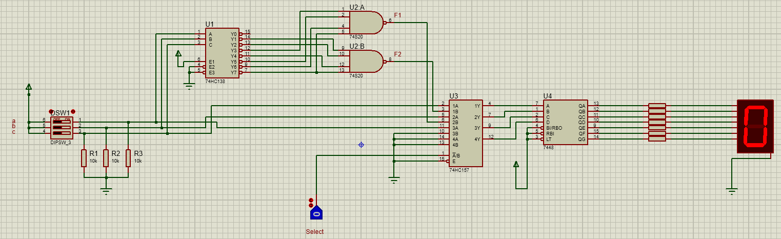
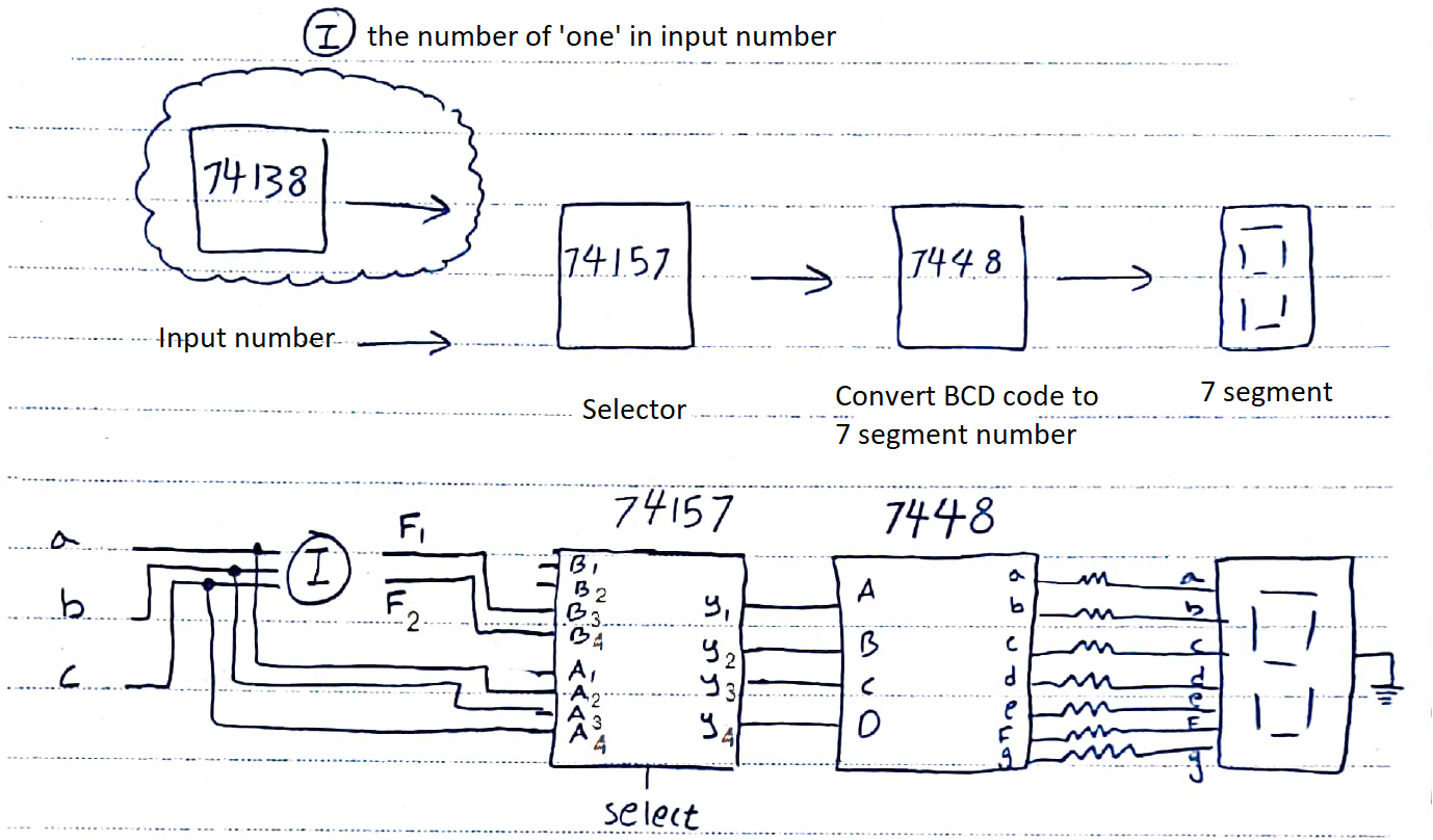
In this circuit, we receive a three-bit input from the user by the deep switch (This number is received in binary form from the user). Then if the selector button is 0, we display the input number on the seven segments, And if the selector number is the number 1, we show the number of one in number on the seven segments. Before we get acquainted with how the circuit works, it is better to first get acquainted with the ICs used in this circuit.
ICs
- 74xx138:
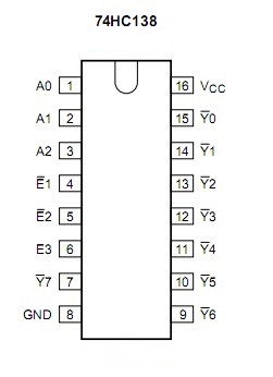 According to the datasheet, this IC can be a 3-to-8 decoder or an 8-to-1 demultiplexer, depending on our needs.Decoder mode:In this case, pins A0, A1, and A2 are the decoder inputs, E1, E2, and E3 are the decoder enable, and pins Y0 to Y7 are the decoder outputs.Demultiplexer mode:
Pins A0, A1, and A2 are our selectors and pins Y0 to Y7 are the decoder outputs. And from the three pins, E1, E2, and E3, one of the two pins, E1 or E2, as inputs, and the other two pins are enabled.
As it is clear from the IC image, the outputs of this IC are active-low.
- 74xx157:
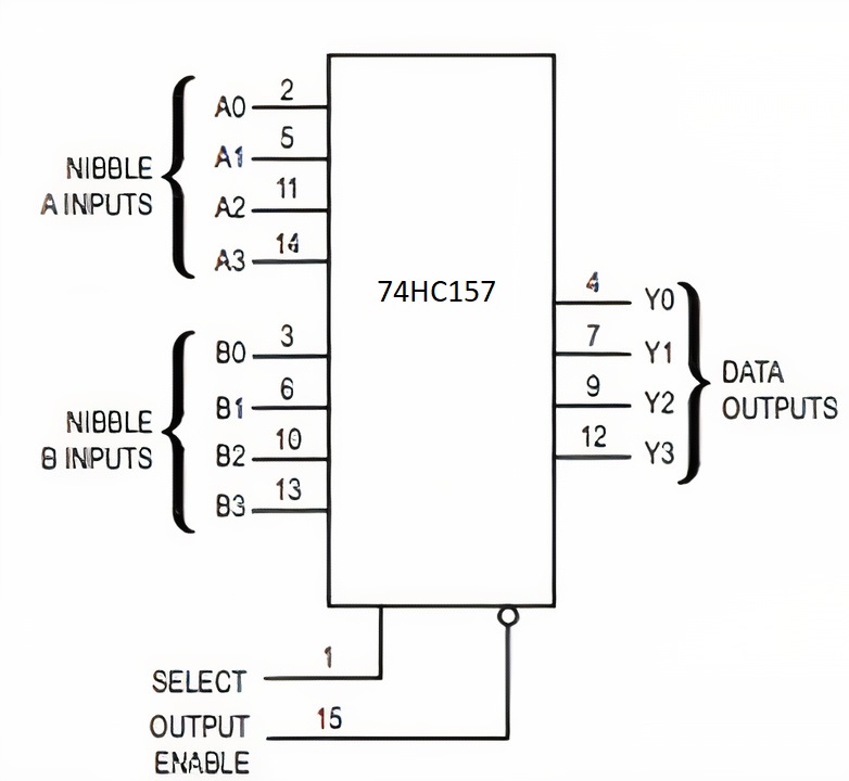
This IC receives two four-bit numbers, and if its select pin is 0, it transmits A; if its select pin is 1, it transmits B to its output. As it is known, the enable pin of this IC is active-low, and for the IC to work, this pin must be connected to the ground. - 7448:
This IC converts the binary number at the input to a display number in the common cathode seven segments. Also, IC 7447 can be used to use the common anode seven segments.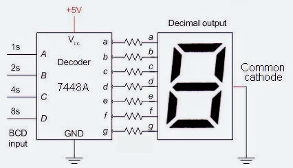
On paper
Before implementing the circuit in the software, it is better to draw and analyze it first on paper. In the first step, we count the number of “one” in the input number, so with the help of 74hc138 IC and the following table we will have:
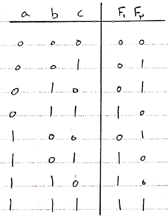
a, b, and c are the decoder inputs, and ‘a’ is at a higher value. F is our desired output that shows the number of “one” in the input. Because our IC is active-low, we use NAND gates to get output.
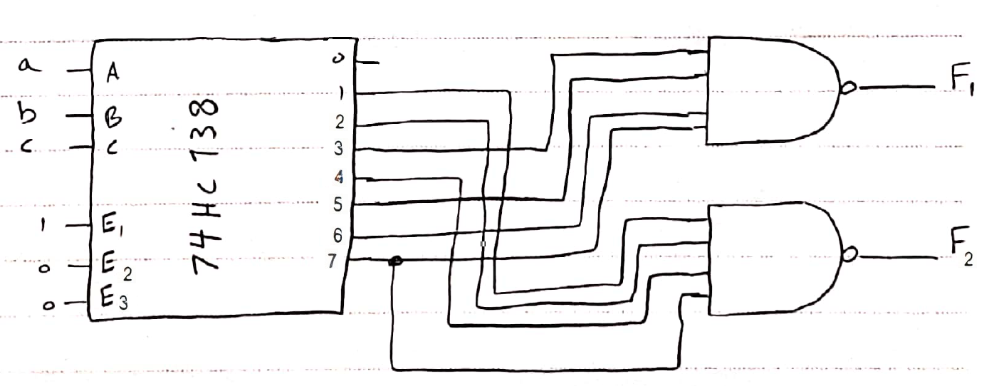
Now we draw an outline of our circuit on paper:
And that’s it!
You can now download the project file here:

.Proteus V8.
Description
university project
April 16, 2021